
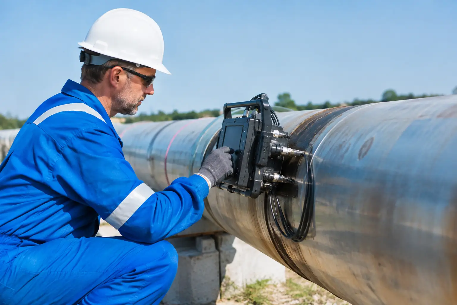
A process line can look sound from the outside while corrosion, erosion, cracking or a failing weld is developing beneath the coating. By the time a leak reaches the surface, the cost is rarely limited to a repair clamp. Production may be interrupted, product can be lost, safety controls triggered and surrounding assets exposed. Pipeline non destructive testing provides the evidence needed to act before that failure becomes an operational event.
For industrial and petrochemical operators, facilities managers and asset owners, the objective is straightforward: establish the true condition of a pipeline without cutting it open, removing unnecessary sections or creating avoidable shutdowns. The right inspection method turns uncertainty into a prioritised maintenance decision.
What pipeline non destructive testing reveals
Pipeline non destructive testing, often abbreviated to NDT, examines pipework and associated components without impairing their future serviceability. It is used on new installations, ageing networks, repaired areas and suspect sections where leaks, pressure loss or process changes indicate a potential defect.
The inspection can identify external and internal corrosion, reduced wall thickness, weld discontinuities, fatigue cracks, pitting, lamination, mechanical damage and coating-related concerns. It can also verify whether a repair has restored integrity before a line returns to service.
No single method sees every defect equally well. A surface-breaking crack, for example, requires a different approach from general wall thinning beneath insulation. That distinction matters. Selecting a test because it is familiar, rather than because it answers the actual failure question, can produce a reassuring report while leaving the critical risk unresolved.
The methods that matter on live assets
Ultrasonic testing is one of the most widely used techniques for assessing pipe condition. A probe sends high-frequency sound waves through the material and measures the returning signal. Thickness gauging can identify wall loss at defined locations, while more advanced ultrasonic methods can assess weld quality and detect discontinuities within the material.
For corrosion programmes, ultrasonic thickness measurement is particularly valuable because it creates a measurable record. Repeating readings at the same test points helps operators calculate corrosion rates, assess remaining wall thickness and plan repairs before minimum design limits are approached. Its limitation is coverage: spot readings are only as good as the inspection plan. Localised pitting can be missed if test locations are too widely spaced.
Radiographic testing uses X-rays or gamma radiation to produce an image of the internal condition of a weld or component. It remains highly effective for certain weld defects and provides a permanent image for review. However, radiation controls, exclusion zones and access requirements can make it less practical in occupied facilities or congested process areas. The operational impact must be weighed against the information required.
Magnetic particle inspection is used on ferromagnetic materials to reveal surface and near-surface discontinuities. After magnetisation, fine particles gather around leakage fields created by a crack or defect. It is a focused technique, often suitable for weld caps, supports and high-stress areas, but it cannot assess the full wall thickness or inspect non-magnetic alloys.
Dye penetrant testing works on clean, non-porous surfaces and is useful for detecting defects open to the surface. A coloured or fluorescent penetrant enters a crack, making it visible after excess material is removed and a developer is applied. It is simple and sensitive, although surface preparation is critical and the method will not identify defects hidden below the surface.
Visual inspection should not be treated as a basic exercise. Performed by an experienced inspector, it can identify failed coatings, corrosion at supports, staining, vibration damage, poor drainage, inaccessible valves, damaged insulation and previous repairs that deserve closer investigation. It is often the first stage of an effective inspection programme, not a substitute for further testing.
Why inspection planning determines the result
The strongest NDT programme begins with the asset, not the equipment. Inspectors need to understand what the line carries, its operating pressure and temperature, material specification, age, corrosion history, repair records and consequences of failure. A chilled water line, fire main, hydrocarbon process line and chemical transfer pipeline do not carry the same risk profile.
Operating conditions shape the likely damage mechanism. Water systems may experience internal corrosion, scale, stagnant sections and joint failures. Hydrocarbon and petrochemical lines may be exposed to corrosion under insulation, sulphide-related cracking, erosion at bends, vibration fatigue or external corrosion in buried sections. Where flow velocities, chemistry or temperature have changed, historic inspection intervals may no longer be appropriate.
Access also influences method selection. A line behind cladding, inside a pipe rack or operating continuously may require carefully targeted testing rather than extensive strip-out. The goal is not to avoid all intervention. It is to remove only what is necessary to obtain reliable data and avoid expensive, speculative work.
From isolated readings to defensible decisions
A thickness reading is useful. A condition assessment that connects readings to design limits, corrosion trends and repair priorities is far more valuable. Decision-makers need to know whether they are dealing with a monitor-only condition, a planned repair, an urgent integrity concern or a potential leak source requiring immediate action.
This is where documented reporting matters. A practical report should clearly identify the inspected line or component, test locations, readings, equipment used, observed defects and supporting images where relevant. It should distinguish facts from recommendations and state any access limitations. If insulation prevented inspection of a section, that must be recorded rather than assumed satisfactory.
For major sites, results should support an asset register and future inspection schedule. Repeating the same survey approach over time creates trend data that can reduce unplanned maintenance. It also helps maintenance teams justify budgets with evidence instead of responding only after a failure.
When leak detection and NDT should work together
NDT assesses the condition of pipe material and joints. Leak detection identifies whether water, gas or process fluid is escaping and, where possible, locates the point of loss. These services are complementary, particularly when a pressure drop or unexplained consumption indicates an active issue but the exact source is unknown.
Acoustic methods can detect the sound created by a pressurised leak. Thermal imaging may reveal abnormal temperature patterns linked to moisture or escaping fluid. Tracer gas testing can locate difficult leaks in buried or concealed pipework, while pressure testing confirms whether a network is holding or losing pressure. Once the likely area is established, ultrasonic inspection or targeted surface testing can help determine the condition driving the failure.
This combined approach reduces demolition and prevents a common mistake: repairing the visible wet area rather than the actual defect. In commercial buildings, industrial facilities and critical utility networks, precise diagnosis protects both the programme and the budget.
Common mistakes that increase pipeline risk
The first mistake is treating an annual inspection as a tick-box exercise. Inspection intervals should reflect service conditions and consequence of failure, not just a fixed calendar date. A low-risk utility line and a critical process line should not receive the same level of attention.
The second is relying on isolated thickness checks without considering corrosion mechanisms or historical trends. A satisfactory result at one point does not clear the whole line, especially around elbows, dead legs, low points, supports and areas beneath damaged insulation.
The third is postponing investigation because there is no visible leak. Many of the most costly failures develop quietly. Early evidence may be a minor pressure decline, increasing make-up water, unexplained pump run time, recurring moisture or repeated small repairs in the same area.
A practical integrity response
When a pipeline shows signs of deterioration, begin by defining the operational question. Is the concern active leakage, wall loss, weld quality, a suspected crack or compliance verification after repair? Then select inspection methods that can answer it, with appropriate safety controls and access planning.
For high-consequence assets, condition findings should feed directly into a repair, monitoring or replacement plan. A temporary repair may be commercially sensible when it buys time for a controlled shutdown, but it should not become an undocumented permanent solution. Equally, immediate replacement is not always necessary when measured condition, operating limits and monitoring support a safe planned intervention.
LeakDtech applies non-invasive diagnostic methods to help clients investigate difficult pipework issues with minimal disruption, supported by clear technical findings for maintenance and repair decisions. The value is not simply detecting a defect. It is giving the responsible team enough certainty to act at the right time, in the right place, before a manageable concern becomes a costly failure.